My F1TENTH Journey — Lab 3, PID-Controlled Wall Follower

This series of blogs marks the journey of my F1/10 Autonomous Racing Cars.
All my source codes can be accessed here.
Previous post:
- My F1TENTH Journey — Lab 1, Introduction to ROS
- My F1TENTH Journey — Lab 2, Automatic Emergency Braking
Lab Materials
The lab materials can be accessed here. A PDF version is also attached here.
The lab was built on the F1Tenth Simulator, which can be accessed here.
PID Control Overview
PID (Proportional-Integral-Derivative) control is a way to maintain certain parameters of a system around a specific set point. It is probably one of the most widely-used yet simple method to maintain a stable system. This lab focuses on implementing a wall-following controller of the simulated F1/10 car using PID control algorithms.
The general PID controller in the time domain can be written in the following way: $$u(t)=K_p e(t) + K_i \int_0^t e(\tau) d\tau + K_d \frac{d}{dt}e(t).$$ where $K_p$, $K_i$ and $K_d$ are tunable weight parameters of the controller, $e(t)$ is the error of current state to the desired state, and $u(t)$ is the control output.
Wall Following
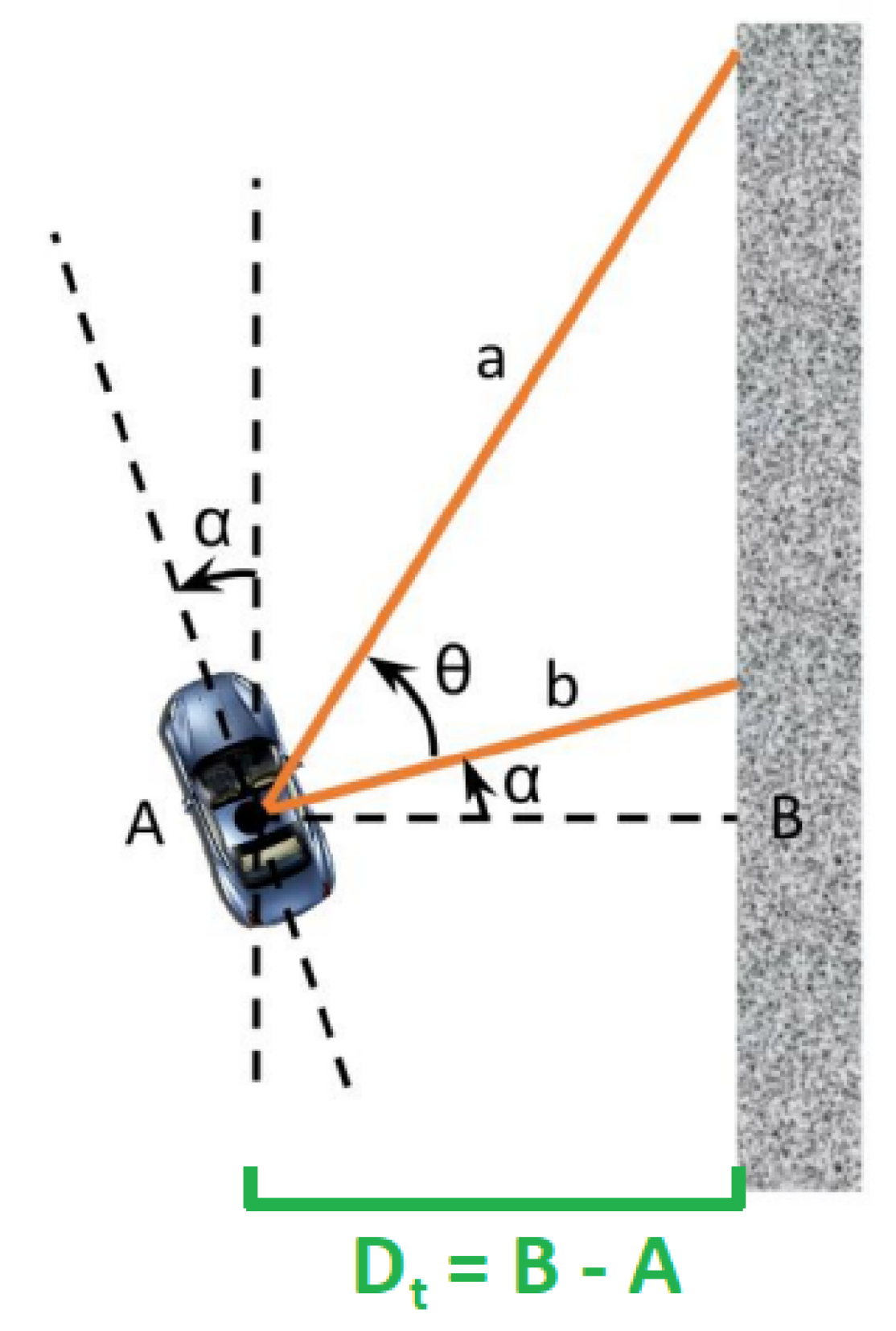
Distance and orientation of the car relative to the wall.
In the context of our car, we would like to maintain the distance between the wall and our car at a certain desired value. In the image above, we can see that the parameter we would like to control is $D_t$, while we only have LiDAR laser scans in the local car coordinate frame (positive $x$ as the forward direction of the car).
In order to calculate the distance from laser scans, we choose a laser ray $a$ and a laser ray $b$ such that $b$ is 90 degrees from the orientation of our car, and $a$ is of some other angle between 0 degree and 70 degrees. Then, from basic trigonometry, we have $$\alpha=\tan^{-1}\left(\frac{a\cos(\theta)-b}{a\sin(\theta)}\right),$$ and then we can express $D_t$ as $$D_t=b\cos\alpha.$$
As we wish to maintain $D_t$ around a certain set point, we define the error term of our PID controller as $e(t)=D_0-D_t$.
What’s more, we would also like to define a look-ahead distance as in real practice our car will be running in high speed and there might be some delays for the car to maneuver as our control command is sent.
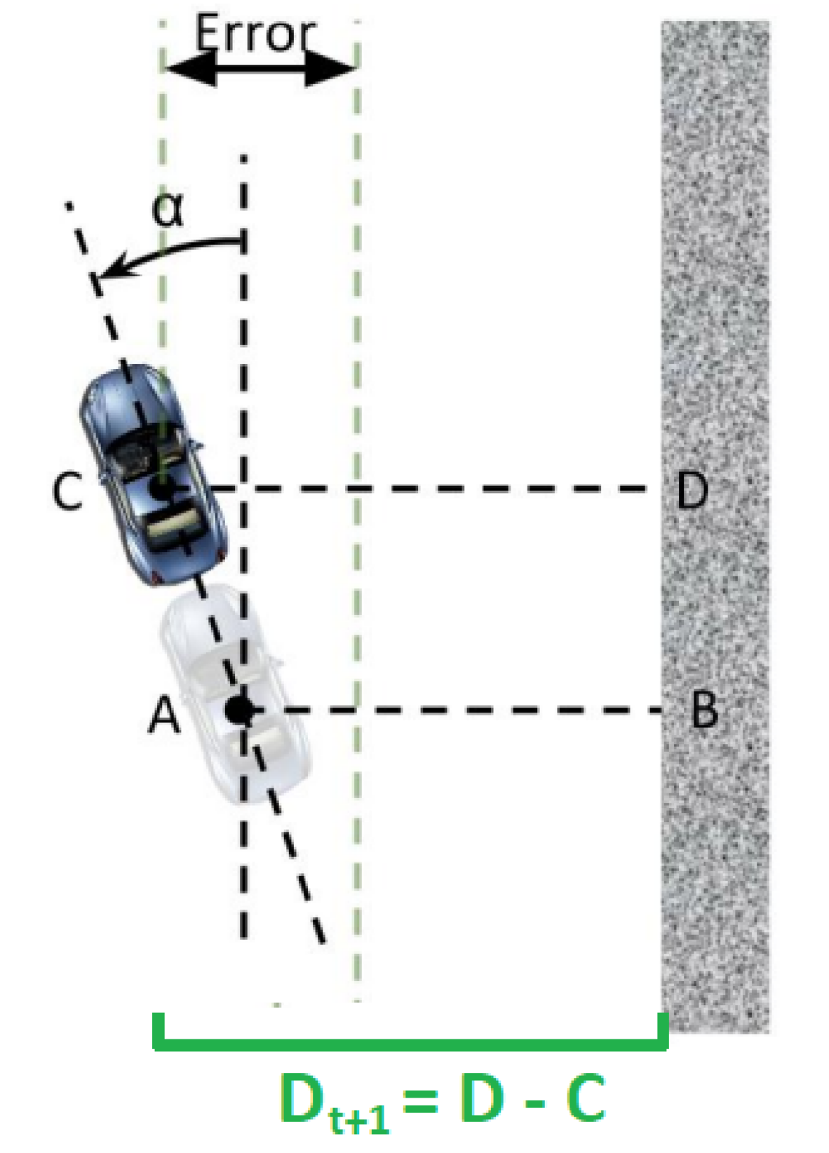
Finding the look-ahead distance from the car to the wall.
The look-ahead distance $D_{t+1}$ can be defined as $D_{t+1}=D_t+L\sin\alpha$, where $L$ is some tunable parameters.
Implementing the PID Controller
With the error term $e(t)$ properly defined, it is not difficult for us to implement the controller. Classical PID controllers are often implemented in a discrete, recursive way, which has the following:
// double integral = 0;  // defined at initialization

double pid_control() {
    double dt = current_time - prev_time;
    integral += error * dt;
    double derivative = (error - prev_error) / dt;

    return K_p * error + K_i * integral + K_d * derivative;
}
PID Tuning
Tuning the PID controller is never an easy task. Sometimes the three parameters $K_p, K_i, K_d$ can be very problematic to tune. From my experience I would try in the following way:
- First, adjust $K_p$ to the maximum gain value (value with max performance), keeping $K_i=0, K_d=0$.
- Second, tune $K_i$ to the maximum gain value.
- Last, tune $K_d$ to eliminate the system oscillations.
We can also use the Ziegler–Nichols method to tune PID controller step by step.
Demo video
This video demos the wall follower without any look-ahead distance. The car would run into the wall at the bottom side of the corridor.
This video demonstrates the wall follower with proper look-ahead distance adjustment, and the car is able to finish an entire loop with no collisions.
References
F1/10 Autonomous Racing Lecture: PID Controller & Laplacian Domain